
Clear and unambiguous annotation of clearance holes on engineering drawings prevents costly manufacturing errors and assembly delays. Despite its apparent simplicity, the clearance hole callout is frequently misinterpreted, leading to undersized or oversized holes that require rework. This tutorial covers the correct annotation format across multiple CAD platforms, including the essential elements that every clearance hole callout must contain.
Essential Elements of a Clearance Hole Callout
Every clearance hole annotation must communicate four pieces of information: the nominal diameter, the tolerance, the referenced standard, and the fit class. Omitting any of these elements leaves room for interpretation. The most common annotation failure is writing “M8 THRU” without specifying that it is a clearance hole rather than a tapping drill size. A correct clearance hole annotation for M8 in the medium fit series reads: “M8 x 9.0 H13 CLEARANCE HOLE PER ISO 273 MEDIUM FIT.” Some shops abbreviate this to “M8 CLR 9.0 MED,” but the full format is preferred for first-article and inspection verification.
CAD Platform-Specific Notation
In SolidWorks, use the Hole Wizard with the clearance hole type selected. The software automatically populates the correct diameter and tolerance based on the selected fastener size and fit class. However, the auto-populated callout often omits the fit class identifier, which must be added manually to the note. Always verify that the Hole Wizard output matches the desired fit class before releasing the drawing for manufacturing.
In AutoCAD, clearance holes are typically annotated using a leader note with multileader style. The recommended format includes the diameter in square brackets for clarity: &osym;9.0 [M8 CLR] MED FIT PER ISO 273. Some organizations add a flag note at the top of the drawing stating “ALL UNMARKED CLEARANCE HOLES ARE MEDIUM FIT PER ISO 273 UNLESS OTHERWISE NOTED.” This approach simplifies the drawing by reducing redundant callouts while ensuring the specification is documented.
In Fusion 360, the hole command includes a clearance option that calculates the correct diameter based on the selected fastener. The generated callout applies GD&T symbols automatically, but the fit class designation must still be verified manually before the drawing goes to production. Regardless of the CAD platform, the engineer should confirm that the annotation matches the ASME Y14.5 or ISO 8015 drawing standard used by their organization.
Positional Tolerance and Datum Reference
A clearance hole annotation on its own does not control the hole’s position on the component. Positional tolerances must be specified separately using GD&T feature control frames. The rule of thumb is that the positional tolerance should be no larger than the clearance hole radial clearance for close-fit applications. If an M8 close-fit clearance hole provides 0.4 mm of radial clearance, the positional tolerance should be &osym;0.4 mm or less to ensure that the worst-case misaligned hole still accepts the bolt. For medium-fit clearance holes, the positional tolerance can be relaxed proportionally. This relationship between clearance and positional tolerance is frequently overlooked, causing precision-assembly failures even when each individual hole measures correctly.
When multiple clearance holes form a bolt pattern, annotate one hole explicitly with its clearance specification and mark the remaining holes with a pattern reference or “TYP” notation. However, avoid overusing “TYP” for clearance holes with different fit classes on the same component. Each unique combination of fastener size and fit class should have its own annotation to prevent ambiguity. For example, a part with M6 medium-fit holes on the top face and M8 close-fit holes on the side face requires two distinct annotations even though all holes are clearance types.
Handling Counterbored and Countersunk Clearance Holes
When a clearance hole is combined with a counterbore or countersink, the annotation must specify both the through-hole and the recess dimensions. The standard format places the through-hole diameter first, followed by the counterbore diameter and depth. Example: “&osym;9.0 THRU [M8 CLR] x &osym;14.0 CBORE x 8.0 DP.” A countersunk clearance hole uses similar notation: “&osym;5.5 THRU [M5 CLR] x &osym;10.6 CSK x 90°.” The countersink depth is typically controlled by specifying the included angle and the large diameter, allowing the machinist to calculate the required cutter engagement.
Counterbored clearance holes serve two purposes: they allow the bolt head to sit flush with or below the surface, and they provide a perpendicular bearing surface that distributes clamping load evenly. Annotate the counterbore depth relative to the surface, not relative to the part thickness, to prevent stacking errors when the part thickness varies within tolerance. clearance hole guides like the cnclathing reference provide both through-hole and counterbore dimensions in a single chart, simplifying the annotation process for common fastener sizes.
Projection and Section View Best Practices
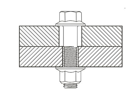
In projections, use hidden lines to indicate the full depth of a clearance hole if it does not pass through the entire part thickness. Blind clearance holes are rare but do appear in applications where the bolt engages threads in a deeper section of the same component. Section views clearly show the relationship between the clearance hole and any counterbore, countersink, or adjacent features. Place the section cut line to reveal the hole’s full profile and mark it with the same annotation as the primary view.
The m8 hole size of 9.0 mm medium fit is one of the most commonly annotated clearance specifications across mechanical design. When applying this callout, verify that the drawing’s title block standard matches the clearance hole standard referenced in the annotation. A drawing produced to ASME Y14.5 but referencing ISO 273 for clearance holes creates a compliance conflict that quality auditors may flag. Most modern CAD templates allow the drawing standard to be selected globally, ensuring consistent annotation formatting across all views and components in the assembly.